What do USB wire codes mean? USB wire codes are standardized color codes assigned to individual wires in USB cables. These codes indicate each wire’s function, such as power, ground, or data transfer. Understanding these codes is critical for troubleshooting, repairing, or creating USB connections accurately and safely.
Content
The Importance of USB Wire Codes
USB wire codes are essential for establishing proper connections in modern technology. Each color code represents a distinct function, ensuring seamless power delivery and data exchange. Without this standardized system, it would be challenging to identify wire roles, increasing the risk of errors, malfunctions, or even damage to devices.
Overview of USB Cable Types
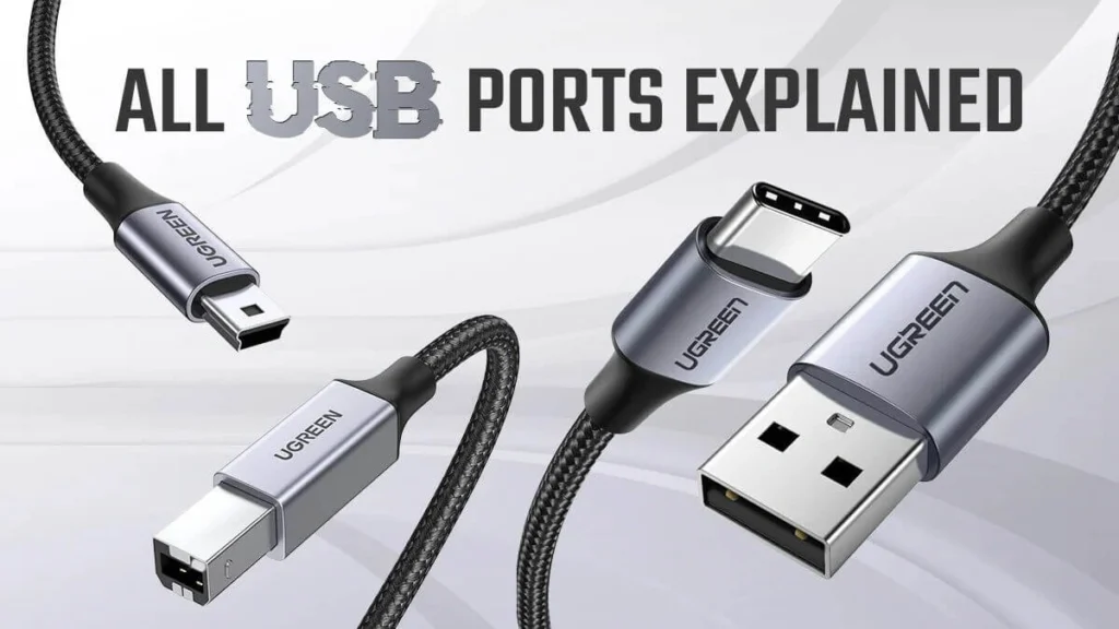
USB cables come in various forms, each designed for specific applications. The most common include:
- USB-A: The traditional connector found in computers, charging blocks, and hubs.
- USB-B: Typically used in printers, scanners, and older external drives.
- USB-C: A versatile and reversible connector used in modern laptops, smartphones, and other devices.
- Mini USB and Micro USB: Compact connectors for older smartphones, cameras, and portable gadgets.
Each cable type has unique USB pin configurations that define its wiring and capabilities. Familiarity with these configurations is essential for effective repairs or modifications.
Decoding USB Wire Color Codes
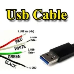
USB cables typically include four wires, each with a specific color and function:
- Red: Supplies power (+5V).
- Black: Serves as the ground wire.
- White: Carries the negative data signal (-).
- Green: Transmits the positive data signal (+).
These colors align with industry standards, ensuring compatibility across devices. In some cases, however, non-standard cables may have additional wires or deviate from these norms. Consulting a reliable USB wiring diagram is crucial in such scenarios.
Comprehensive Guide to USB Pinouts
USB pinouts refer to the electrical contacts within a USB connector. Each pin serves a designated purpose, such as providing power or facilitating data transfer.
USB-A Pinouts
- Pin 1: Power (+5V)
- Pin 2: Data (-)
- Pin 3: Data (+)
- Pin 4: Ground
USB-B Pinouts
The configuration is similar to USB-A but adapted for larger peripheral devices.
USB-C Pinouts
Modern USB-C connectors feature up to 24 pins, supporting higher data transfer rates and power delivery capabilities. This complexity enables advanced functionalities like video output and fast charging.
Accurate USB connector pin diagrams are invaluable for identifying the roles of individual pins, particularly for more intricate connectors like USB-C.
Creating and Interpreting USB Wiring Diagrams
Understanding a USB wiring schematic is a valuable skill for anyone working with electronics. These diagrams visually represent the connections between wires and pins, enabling precise assembly or troubleshooting.
To create a custom diagram:
- Determine the type of USB connector and its intended use.
- Reference standard USB pin configurations for accuracy.
- Clearly label wires and pins to avoid confusion.
- Test the diagram before implementing it in a project.
Properly labeled diagrams simplify complex tasks, such as modifying cables for specific devices or diagnosing wiring issues.
Addressing Common USB Wiring Issues
Wiring problems are a frequent source of frustration in USB cable usage. Issues can include broken wires, incorrect connections, or deviations from standard USB wire color meanings.
To resolve these challenges:
- Use a multimeter to check wire continuity and voltage.
- Compare the wiring to a trusted USB cable wiring guide to identify errors.
- Replace damaged components when necessary to restore functionality.
Proactively addressing these issues ensures reliable performance and prevents further complications.
Practical Applications of USB Wire Codes
USB wire codes are indispensable for various tasks, including:
- Custom Cable Assembly: Building cables tailored to specific requirements.
- Device Repair: Diagnosing and fixing connectivity issues.
- DIY Projects: Integrating USB technology into innovative designs.
By understanding the nuances of USB wiring schematics and pin configurations, enthusiasts and professionals alike can confidently tackle these challenges.
Conclusion
Mastering USB wire codes, pin configurations, and wiring diagrams empowers users to handle a wide range of USB-related tasks. This knowledge not only ensures safe and efficient connections but also unlocks opportunities for innovation in electronics. With this comprehensive guide, you are well-equipped to navigate the complexities of USB wiring with confidence.
Frequently Asked Questions about USB Wiring
What do USB wire colors mean?
USB wire colors follow a standardized scheme where red indicates power, black serves as ground, white carries the negative data signal, and green transmits the positive data signal.
How can I test a USB cable?
A multimeter can verify continuity and voltage across the wires, confirming their integrity.
Are USB pinouts the same for all cables?
No, pinouts vary depending on the USB type. USB-C, for example, has a more complex pin configuration than USB-A or USB-B.

I’m Kelly Hood! I blog about tech, how to use it, and what you should know. I love spending time with my family and sharing stories of the day with them.

